Since I started using the Raspberry Pi as a radio tracker, I’ve been wanting to try two things both in the interest of reducing payload weight. As a simple telemetry tracker the Pi just cannot compete on weight with say an Arduino Mini Pro, which weighs almost nothing and has low power requirements, but as a photographic tracker it starts to come into its own.
This two things were the model A Pi, which has been available for a few weeks, and the new Pi camera which a few lucky souls (including me) have been sent pre-production models of. The model A has about 1/4 of the power consumption of the model B, thus potentially (hah!) using smaller batteries. The camera is a lot lighter than a webcam whilst using about the same power, and doesn’t connect by USB meaning that I can dispense with the 5V rail altogether (saving the weight of a 5V regulator and allowing the use of fewer batteries. A lighter payload means less gas which in turn means a greater peak altitude before the balloon bursts, meaning a good chance of beating the “live” picture altitude record and perhaps the “highest pictures” record too.
The Pi camera also offers much higher resolution than the webcam I was using, though the limited radio bandwidth means that such images would need to be stored only and not transmitted. However I still wanted to take advantage of the increased picture quality over a webcam, and that means increasing the radio bandwidth. First option is to increase the baud rate, so for my TARDIS flight I tested that by doubling the rate from the 300 baud of my earlier Pi flights to 600. Practically, that’s practically as high as I can go with the existing rtty system since 1200 baud uses almost the entire audio bandwidth of the decoding software, thus making it very difficult for receivers to remain tuned in. Then Anthony Stirk came up with the idea of using 2 radio transmitters on the same tracker, to either interleave a picture between 2 radio frequencies or to send separate pictures on each. Either way the end result is double the amount of image data being sent, and I thought it was a brilliant idea. After a quick chat with Philip Heron (who wrote the SSDV imaging software I use to encode/decode the images for transmission) to confirm that his system would work using either method, I set about making it happen.
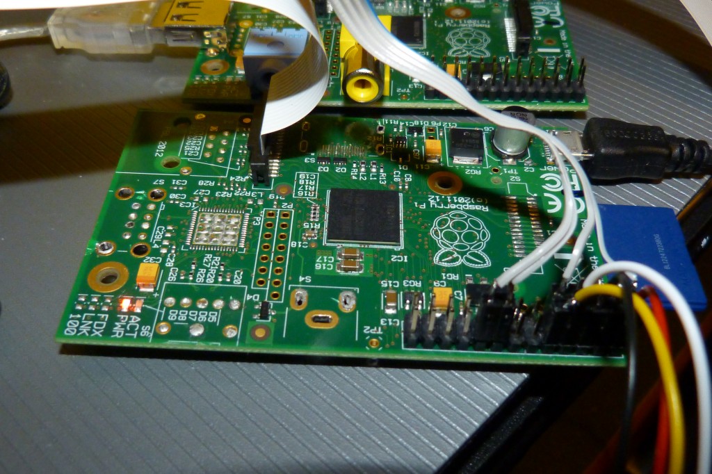
Now, my method for transmitting rtty from the Pi is to connect the serial (UART) port more-or-less directly to a Radiometrix NTX2 radio transmitter, thus avoiding the need for application software to maintain accurate timing. Although the Pi has 2 such ports, only one can be mapped to the GPIO connector at a time, so I needed some other technique to get both radios running. My solution was to add an Arduino Mini Pro as a de-multiplexer so, essentially, telemetry gets sent at double speed to the Arduino which then sends packets to the correct NTX2. The coding was a bit more complex than that, with the Arduino maintaining 2 buffers (1 for incoming and one for outgoing) per radio channel, and handling a simple protocol with handshaking, the result of which is no gaps between transmitted packets thus making full use of the available bandwidth. Here’s the Arduino wired up:

to two of these NTX2 radio transmitters

Here’s the model A Pi. Note that most of the connectors are missing (save more weight!):
and the pre-production Pi camera in action:

For GPS, I used a minature UBlox breakout board from HAB Supplies, hacked to connect via i2c instead of async serial:

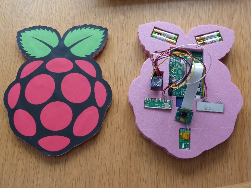
and the lot is going into this themed payload container:

like so:
Looks fantastic, Dave. Nice to see someone else using the camera 🙂
When do you think you’ll launch?
Just as soon as diaries and wind predictions come together 🙂
Really interesting project. Would love to come and see it in action.
Question instead of a huge antenna is their away of using a drone to transmit the data to a ground station using a relay method ? , so we can raise / lower , and use directional antennas to increase range and data bandwidth , thus it also can become mobile – Martin
Too complex, and you don’t need a huge antenna, just a bit of height.
There’s only 3 wires going to the radio modules, which I’m guessing is PWR, GND and TX? If that’s right, and they don’t need a RX signal, then according to http://elinux.org/RPi_BCM2835_GPIOs if you desolder R21 (part of the audio output circuitry) then you should be able to get access (assuming you’re able to solder anything to a pad that small) to TXD1 via the ALT5 function of GPIO40 ?
Which should then allow you to drop the Arduino Mini from your setup…?
Alternatively at such slow baud rates, you might be able to bit-bang a serial port just using regular GPIO pins?
And on the subject of saving (even more) power, I guess it might be an interesting experiment to see if the camera-module still works if you underclock your RasPi?
And as you’ve already performed such drastic surgery on your RasPi, I guess you could also replace the full-size SD card holder with a MicroSD equivalent? 😉
Unfortunately, that doesn’t help, since ALT5 disconnects the other serial port. As far as I can tell there aren’t any mappings where both serial ports are accessible at the same time.
I would *love* to be proved wrong here!
I can’t wait to this in action, and to also see the resulting images!