One of the advantages of the LoRa transceivers, when compared to the traditional RTTY modulation used by most High Altitude Balloons, is that it requires very little processing power at the receiver. So instead of using a PC or a high end tablet or phone to decode the transmissions, all you need is a simple microprocessor with (assuming you want to upload data to the web for mapping) an internet connection.
The latter requirement makes devices such as the Raspberry Pi ideal for the task. A Pi, plus wired or wireless connection, just needs a simple board added with a LoRa transceiver connected to the SPI pins. And that’s exactly what Uputronics has made – and here’s a prototype board that they sent to me:

Normally it comes with a single 434MHz LoRa device but here I’ve added a second (you could add a 434MHz or 868MHz model). The remainder of this post will assume that the board is populated with just one device, in position 1.
Physically install is very simple – just push on to the Pi model A+ or B+, using a standard pin header extender (supplied). Or an pin header with extended pins can be used if you want to stack another board on top.
Next, burn an operating system onto a suitable SD card. For this purpose anything from 4GB should be fine. The following instructions are for Raspbian, and no other operating systems have been tested.
First, run raspi-config:
sudo raspi-configThen expand the filesystem, as you would normally do, then choose Advanced Options –> SPI and enable SPI.

It’s also worthwhile to change the hostname (Advanced Options –> Hostname). Finally, close the program and choose the reboot option.
Once rebooted, login again. We now have some software to install. First, install wiringPi, which is used for the SPI library and to read the status of the LoRa module via 2 of its INT pins:
cd ~
git clone git://git.drogon.net/wiringPi
cd wiringPi
./build
Next, install SSDV which is used to decode download images:
cd ~
git clone https://github.com/fsphil/ssdv.git
cd ssdv
sudo make install
The gateway software uses the curl library for internet access (uploading telemetry data and/or image data), so install that:
sudo apt-get install libcurl4-openssl-devand the ncurses library used for the screen display:
sudo apt-get install libncurses5-devFinally, install the gateway software itself:
cd ~
git clone https://github.com/PiInTheSky/lora-gateway.git
cd lora-gateway
make
That completes the installation, so now for the configuration. The main settings are in a file gateway.txt in the above folder (/home/pi/lora-gateway). Here’s a simple example:
tracker=MYCALLSIGN

frequency_0=434.451
mode_0=2

#frequency_1=434.450
#mode_1=0
This firstly sets your callsign, which if you are a radio amateur would normally be your radio callsign, but it can be something else.
The next part sets the frequency and mode for the first LoRa device (the one in position “1”). Frequency is in MHz and should match the frequency of the tracker that you intend to receive. “Mode” is described below, where the other (optional) settings are also described. The final lines are commented out, to disable the second LoRa module.
tracker=<callsign>.  This is whatever callsign you want to appear as on the tracking map and/or SSDV page.

EnableHabitat=<Yes/No>.  Enables/disables telemetry upload to habitat.

EnableSSDV=<Yes/No>.  Enables/disables image upload to the SSDV server.

frequency_<n>=<freq in MHz>.  This sets the frequency for LoRa module <n> (0 for first, 1 for second).  e.g. frequency_0=434.450

mode_<n>=<mode>.  Sets the "mode" for the selected LoRa module.  This offers a simple way of setting the various
                LoRa parameters (SF etc.) in one go.  The modes are:

                0 = (normal for telemetry)  Explicit mode, Error coding 4:8, Bandwidth 20.8kHz, SF 11, Low data rate optimize on
                1 = (normal for SSDV)       Implicit mode, Error coding 4:5, Bandwidth 20.8kHz,  SF 6, Low data rate optimize off
                2 = (normal for repeater)   Explicit mode, Error coding 4:8, Bandwidth 62.5kHz,  SF 8, Low data rate optimize off
                3 = (normal for fast SSDV)  Explicit mode, Error coding 4:6, Bandwidth 250kHz,   SF 7, Low data rate optimize off

SF_<n>=<Spreading Factor>  e.g. SF_0=7

Bandwidth_<n>=<Bandwidth>.  e.g. Bandwidth_0=41K7.  Options are 7K8, 10K4, 15K6, 20K8, 31K25, 41K7, 62K5, 125K, 250K, 500K

Implicit_<n>=<Y/N>.  e.g. Implicit_0=Y

Coding_<n>=<error_coding>.  e.g. Coding_0=5 (4:5)
To run, just type
sudo ./gateway
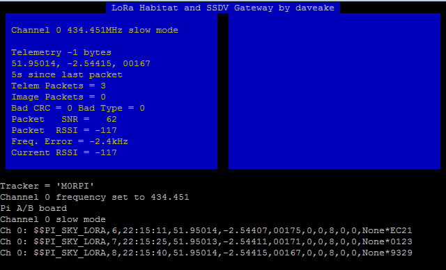
and you will see a screen like this:

In this example, channel 0 (the LoRa module in position 1 on the board) is enabled, at 434.451MHz, and mode 0 which is a shorthand for a mode suitable for continuous long-range telemetry transmission.
The status display updates as packets are received:
Finally, to exit the program, press CTRL+C.
Dave, have you found the sensitivity of the LoRa Tx/Rx is better than a standard Radiometrix module with RTTY?
I’ve not had a flight far enough away to know, but my guess is that they’re comparable. I’ll have a better idea after more flights. The main question though is how well LoRa works in a chase car, as that’s the most important receiver when trying to retrieve a flight.
Hi Dave, you write: The next part sets the frequency and mode for the first LoRa device (the one in position “1”). I assume that, with markers on my board CE0 and CE1 that the first line sets Frequency_0 for the device in slot CE0 and that Frequency_1 sets it for the device in slot CE1. Am I right ? I have a Pi addon board with one LoRa module in CE1, My RSSI with no signal , with frequency_0 is constant -157 and if I use Frequency_1 it’s -116 and showing changes when I disconnect the antenna. There is no error message callign a frequency on a not installed LoRa module.
By the way, is there a way to have a test transmission myself with only the Pi and the LoRa board ? I would like to see my own signal on the SDR receiver….
Kind regards,
Ben
Hi Dave,
I’ve a question regarding LoRa: all examples we’ve found with LoRa are about the use of the LoRa module with an Arduino, a Raspberry and so on.
On the other side, example about using Xbee show that we can use Xbee also with Arduino (or Raspberry) but that it’s also possible to use the Xbee alone.
As we are working on a project on which the receiver must only light a LED, we’re interesting but a stand-alone system (so like “Xbee alone”).
The question is: is it possible with a LoRa module?
Thanks for your answer
Kind regards
Pierre-Louis
For a simple PICAXE-08M driven proof of concept (& LoRa™ overview) perhaps see => http://www.instructables.com/id/Introducing-LoRa-/
There is a simple lora module tutorial for HAS application. The range is up to 56km long.
see=>http://www.appconwireless.com/NewsShow.asp?id=207
Range with these transceivers when airborne is, effectively, just limited by line-of-sight, and some of my flights have achieved 400km+ range at altitudes of 30km or so.
Hi Dave, I am unable to complete the command ‘ $ sudo ./gateway ‘. Any suggestions/advice from there?
Thanks!
‘Failed to open config file’ is what I got.
Hope to get a reply from you soon. Thanks so much!
Hi, I’ve solved this problem and I’ve encountered another. How do I connect the device to the gateway? In another words, how do receive the data from the device?
Hope to hear from you. Thanks!
I don’t understand your question.
It receives data from balloon trackers (e.g. this one http://www.pi-in-the-sky.com/). It does this using a LoRa board such as the one shown in my article. Received packets are uploaded to the balloon tracker and appear on the balloon map (https://tracker.habhub.org). So the entire process is:
GPS data at tracker –> LoRa board on tracker ——————-> LoRa board on Pi gateway –> Balloon map
So you need balloon tracking software, a Pi and LoRa board for the balloon tracker, a Pi and LoRa board for the gateway, and of course my gateway software.
Hope this is clear.
Dave
Will your tutorial work with this shield?
http://wiki.dragino.com/index.php?title=Lora/GPS_HAT
Best, thx!
If the DIO0 and DIO5 pins are brought out to the PI, then yes it should work. You would need to configure the software for whichever pins those are connected to.
Looks like only DIO, DIO1 and DIO2 are hard wired to the Pi GPIO pins:
https://github.com/dragino/Lora/tree/master/Lora_GPS%20HAT/v1.3
Thankfully DIO 0 through the to 5 are presented as pins on the HAT, would it simply be a case of wiring at least DIO5 to an unused gpio pin?
Discussion continued on github:
https://github.com/PiInTheSky/lora-gateway/issues/31
good evening, can i know if there is any possible information for me to simulate this LoRa transceiver using Simulink? is there any white papers that could help me design the block diagram using Simulink? sorry but this could help me do my final year project.
Can i do this without the use of Lora?
Thanks Dave.
I wonder what else is needed to get duplex comms working, e.g. for early flight termination..?
There are modifications in the works to do this.
I would like to install a LoRa getaway in my supervisor truck, so when passing close enough of a truck equip with a gps data logger, that the data will be received in the supervisor equip with getaway and a laptop and transfer those data to our server. The idea is to avoid using cellular network and fees.
Can you help
Hi Dave, I just managed to receive data from a “DIY Lightweight Pi Tracker with SSDV” to a “lora gateway” (raspberry pi3B + lora board from uputronics). I also found my test images on ssdv.habhub.org.
I’ve noticed that often, if I start the receiver while the transmitter is already running, I only receive CRC errors. The only way to clear the problem seems to be stopping and restarting the transmitter. After that, the receiver starts displaying valid packets. Then, if I stop / restart the receiver, chances are that I will run again into CRC errors.
The worry is: if for any reason I need to restart the receiver while the transmitter is in flight, I wouldn’t be able to reset it.
Is this a known problem? Should I post my configuration? (btw it’s the default you provided for the DIY Pi Zero project).
Also: I’d like to have a gateway capable of displaying / storing images locally and also display a chasing map. I’ve seen the “Portable Lora Gateway” project, but it’s quite dated (2015) and I’m unable to find information about how to add the LCARS interface to the standard gateway. May you point me to the right direction?
Thanks a lot and Best Regards!
Alessandro, Italy
Hi Dave,
I have recently attempted a high altitude balloon launch using LoRa to transmit GPS location and altitudes. I found that the range for the LoRa only reached about 20 kilometers before it died. I was wondering what sort of antennas you use for your transmitters and receivers and if you use signal amplifiers on any of these. I’m in the USA so I use 915 mhz. I’d love to hear from you about what I can do to improve my range.
All the best,
Aidan Saltz Burke
Hi Dave,
I have made the Lora Gateway usinga Raspberry Pi 4 and the RFM Breakout and all seems to be working fine.
I would now like to build another gateway using a pi zero and RA02 will the commands be the same for the RFM chip and the RA02 chip or will the code need changing? (I have 2 RA02 chips bought before finding this tutorial so would like to use them aswell if possible)
Thanks
Marc
Should be fine. Any board with the SX1278/1276 that brings out the SPI and DIO0 pins should work. Pi Zero is fine also.
Perfect cheers for the fast response.
Hi Dave,
I’m working with a group at my high school focused on sending a high altitude balloon into the stratosphere. I’m trying to find a way to send live pictures down to the ground and thought you might be able to help. Do you think that LoRa will be powerful enough for this purpose, and how far do you think it will be able to transmit? How much will a Yagi antenna increase the range?
Thanks for your help,
Levi
Hi Dave,
I was trying to input the code into my Pi and received a few problems after:
cd ~
git clone https://github.com/PiInTheSky/lora-gateway.git
cd lora-gateway
make
I got a few overload messages and a fatal error when it was not able to locate curl/curl.h
Do you have any idea why this is?
Thanks,
Levi
Dude did you install this first
sudo apt-get install libcurl4-openssl-dev
Hi Dave, I hope you are well. Some awesome work you do. If you follow these instructions now for the lora gateway using a pi zero W2 when I cd lora-gateway and then make I get a fatal error then something about “MQTTClient.h” I did a few installs and then it changed to “paho.mqtt.c” I had this problem ages ago and I don’t know how I even sorted it out. It’s frustrating. ????
For posterity, I fixed this problem by running “sudo apt install mosquitto-dev” to install the Mostquitto development files.