When used for tracking high altitude balloons, LoRa has the potential for a receiver to be set up unattended on a permanent basis, but only if it can automatically set itself to the correct frequency, bandwidth and other settings for each flight. Originally I intended these settings to be taken from a central database, but a rather neater solution was suggested yesterday on the #highaltitude IRC channel. During a discussion of how to solve this problem, Philip Heron of SSDV fame suggested that each balloon announce its own parameters on a standard calling channel:
[15:45] <fsphil> I'd like a channel for announcements
[15:45] <fsphil> "I'm on xxx MHz with these parameters"
Neat idea.
Fast-forward 24 hours to now, and I’ve coded this up in the LoRa section of my Pi In The Sky tracker software and also my LoRa gateway. It wasn’t difficult and took about 3 hours altogether.
The tracker is configured with 2 settings:
LORA_Calling_Frequency_0=433.650
LORA_Calling_Count_0=5
The first setting specifies a calling frequency on which the tracker will periodically transmit a message telling listeners the frequency and parameters of its normal transmissions. The second setting specifies how often this special message is sent (e.g. after every 5 normal messages). The other parameters of this special message (bandwidth, spreading factor etc.) are fixed at present (probably a good idea for a calling channel!):
EXPLICIT_MODE
ERROR_CODING_4_8
BANDWIDTH_41K7
SPREADING_11;
The message itself is very simple, e.g.:
^^PI_SKY_TEST,434.400,0,8,48,176,8*B30C
and contains the payload ID, frequency in MHz, implicit/explicit mode, error coding, bandwidth, spreading factor and low-data-rate optimisation.
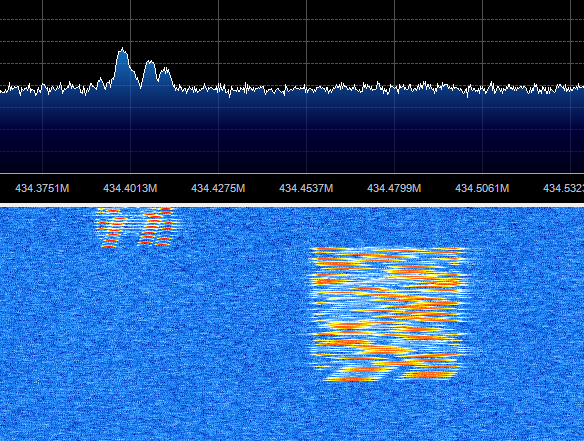
Here’s a sample packet seen on an Airspy SDR. The calling packet is the one on the right (at 434.475MHz), followed by the start of a normal packet (on 434.400MHz):
The gateway has of course to be set to the calling frequency (434.475MHz in this case) and the correct set bandwidth etc. which are combined to together into a new “mode” of 5. I have also enabled AFC (Automatic Frequency Control) using code written by David Brooke (thanks David!) – you can see his version of my LoRa gateway here.
frequency_1=434.475
mode_1=5
AFC_1=Y
The gateway shows the following screen when started:
 Note that it says “Calling mode” at the top, next to the calling channel frequency.
Now let’s see what happens when it receives a calling packet:

The final message in the log at the bottom states that the new frequency is 434.405MHz; why not 434.400MHz as requested by the tracker? The reason is that the receiver detected a frequency error of 4.6kHz (see the frequency error shown near the bottom of the blue section on the right). As we have AFC enabled, the software automatically applied this error when it switched to the balloon tracker’s main frequency. It’s better to do it now rather than later, especially if (as in this case) the balloon’s main transmission is using a narrower bandwidth where a large frequency error might prevent any packets being received.
So, now the gateway has tuned in to the balloon’s main frequency, and set the various LoRa parameters correctly, it should start receiving regular packets:
 In this screenshot, it has received 13 such packets so far. You may also notice that it has fine-tuned itself to the balloon main frequency, and now has a zero frequency error.
Dear Dave Akerman
You have nice webpages indeed.
I am the student in JAMK university of applied science in Jyväskylä, Finland.
I am making the final examination of LoRa and use of it in IoT.
I have 2 Raspberry PI and HopeRF RFM96 (868MHz) on it.
Now I am wondering what is the best way to test coverage,
battery lifetime, bit rates and so on with this combination.
Maybe I could also try balloons with testing.
Have you any idea how to carry on?
Br. Kimmo Lepoaho (OH6LDK)
K5864@student.jamk.fi
ps. I would mention your work in my final examination.
pss. So I know also what RTTY, APRS means
Balloons have an advantage because they have line-of-sight to between the air and the ground; IOT does not always have that. So balloons are not a good way to test the range on the ground.
You could set up a ground test with aerials a certain distance apart, with LOS or with buildings in the way, and test at different power and bandwidth and other settings.
No doubt Semtec have lots of data about this. Also they have a calculator which shows power consumption which you could use to calculate batter life.
Has this been implemented in the PITS software?
I see some references to it in some parts of the code, but I am not good enough at C to really understand if it is what I think it is!
Yes, with LORA_Calling_Frequency_[n]=[frequency] where [n] is the LoRa channel 0 or 1.
Hello, I tested this feature and it works very well.
I was wondering that once the gateway receives a calling packet and switches to the new frequency/mode, it then becomes deaf to other trackers, requiring manual restart to go back to calling mode.
Since the gateway can have two LoRa modules, wouldn’t it be better if one could set one module to calling mode (forever) and have a calling packet setting the other one?
This way, one could place a gateway on the roof and leave it alone, waiting for balloons to help without intervention.
Thanks in advance for any comment
Alessandro, Italy
p.s. I don’t see the “SSDV” or “Calling mode” text at the top, after the channel frequency, as described in the article. I’m running “LoRa Habitat and SSDV Gateway by M0RPI, M0DNY, M0RJX – V1.8.30” from piinthesky, but the same happens if I try the ‘dbrooke’ fork.
It does time out after a set period once the balloon can no longer be heard, so no need to restart.
For a receiver with 2 modules, a better option would be if both were set to calling mode, then one switches to the tracker’s settings leaving the other waiting for the next balloon. That’s not programmed at present.
The gateway no longer displays the text description for the mode.
Sorry,
I just noticed that after one minute of silence, the channel goes back to calling mode, but it keeps the frequency shift of the “previous balloon” (i.e. it went to 434.473.5 instead of 434.475, I don’t know if this is a good thing).
I also noticed that if I set a tracker to send the calling packets (434.475MHz), then a gateway seems to be able to detect them even if not configured to do so.
Example: tracker with frequency set to 434.202 (it has a known shift of -2kHz) and calling mode enabled (434.475MHz).
If I set the gateway (both channels) to receive on 434.200 and I start the tracker, both channels will receive a calling packet (!!!) and move to 434.202, being unable to decode anything else (CRC errors because of the frequency shift). After one minute, they both go back to calling mode (which is not configured) and, this time, they correctly tune to 434.200, starting normal reception.
Maybe the calling packet is also sent on the “standard” frequency?
Tracker = ‘NASD086C1’
Channel 0 frequency set to 434.200MHz
LoRa Channel 0 DIO0=6 DIO5=5
Channel 1 frequency set to 434.200MHz
LoRa Channel 1 DIO0=27 DIO5=26
Listening on JSON port 6004
Starting now …
Uploaded listener NASD086C1 19:54:15,44.746410,11.012794
Retune by 0.8kHz
Ch 1: Calling message, new frequency 434.202
Ch 0: Calling message, new frequency 434.203
19:54:24 Ch1: $$NASD01,1,00:00:00,0.00000,0.00000,00000,0,0,0,46.5*769D
Ch1: CRC Failure, RSSI -106
Ch0: CRC Failure, RSSI -109
Ch1: CRC Failure, RSSI -107
Ch0: CRC Failure, RSSI -109
Ch0: CRC Failure, RSSI -108
Ch1: CRC Failure, RSSI -106
Return to calling mode
Return to calling mode
Ch 1: Calling message, new frequency 434.202
Ch 0: Calling message, new frequency 434.203
19:58:45 Ch0: $$NASD01,1,00:00:00,0.00000,0.00000,00000,0,0,0,45.5*2FCD
Retune by -2.3kHz
Retune by -2.1kHz
19:58:46 Ch1: Null uplink packet
19:58:46 Ch0: Null uplink packet
Retune by -2.2kHz
19:58:48 Ch0: $$NASD01,2,00:00:00,0.00000,0.00000,00000,0,0,0,45.5*9053
Retune by 2.4kHz
Retune by 4.8kHz
Thanks!
Alessandro
There is no specific calling mode; the program will accept a calling mode message on whatever frequency/mode it is set to. For the UK we settled on 433.650MHz and mode 5, but there’s no general standard.
Yes it should reset the offset when resetting frequency/mode.
Thanks, this explains many things and maybe I understood what happens here:
the ‘calling message’ is received by a gateway which is not configured on that frequency only ONCE and just when the tracker is started.
Hence, my idea is that the tracker, at startup, sends the first ‘calling mode’ packet using the ‘normal’ (telemetry) frequency (i.e. 434.200 in my setup) instead of 434.450.
This is why I get that message on the gateway configured in mode=1 on 434.200.
May it be so?
I confirm that the gateway does not reset the offset when restoring frequency to calling mode (when the “Return to calling mode” message is displayed). For example, these are the values restored after one minute of silence (tracker shut down) for my two modules:
Channel 0 434.648.5 MHz
Channel 1 434.647.5 MHz
I set my calling mode frequency to 434.650, just in case your balloon spans over north Italy 🙂
Thanks a lot for the patience and Best Regards
Alessandro