For a while I’ve wanted to build a “Flight Readiness” unit that I can have near me when filling a balloon, and will show me if the tracker is running OK or if there’s a problem with the tracker or receiver (e.g. it may have drifted out of tune). To build this I needed a WiFi-connected computer (a Raspberry Pi is an obvious choice) plus a display that is easily visible in a variety of lighting conditions. I opted for an “LED badge” which is a small scrolling message board, purchased on ebay for £13 (about $20).
![]()
These displays typically have a USB socket for charging and programming, and appear to a PC or Pi as a virtual serial port. They come with Windows drivers and software to download messages to the device, the intention being that you download your message then unplug and run the display from its internal battery. Messages are stored internally in flash memory so the device can be powered off and it will retain the message.
For my purposes, I want to be able to send a message from a Pi, and have the device display that message (scrolling if necessary) until I replace the message with another one. I can then get the Pi to display the current tracker status – e.g. “All OK”, or “No GPS Lock”, etc.
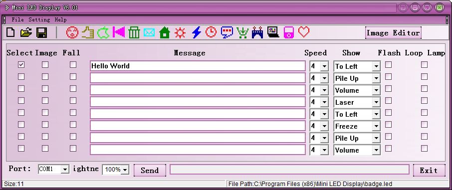
So the first job was to get the device running on my Windows PC. The device installed as a serial device (the common Prolific PL2303 driver) and the supplied software successfully sent messages to it:
So with the software working, the next job was to have a look at what it was sending to the device. For this I downloaded a serial monitor program from HHD Software. This is an excellent program and runs for 14 days in trial mode with nag screens. For the above message and settings it showed this packet being sent, at 1200 baud:

Perhaps surprisingly, the “hello world” text doesn’t appear. In fact, this is because the PC is rendering the text and sending it as a 1-bit bitmap pattern. By sending different messages with different parameters (brightness, scroll speed, direction and “loop” which is a marquee effect) I gleaned the following about the protocol:
- The first item is a 6-byte startup packet “Ahello”
- This must be followed by a short delay (10ms works well)
- The next 48 bytes contain the message parameters and the number of bitmap packets.
- This must be followed by a delay of at least 800ms
- The bitmap packets follow, 11 bytes each, with a delay of at least 100ms separating each from the next.
The parameter section can be adjusted as follows:
- Byte 0 (the first byte of the parameter packet) has the brightness in bits 2-0. Value 0 is the brightest and 3 the dimmest.
- Byte 2 has the following:
- Bit 7 is set for the marquee effect
- Bits 6-4 contain the speed from 0 (slow) to 7 (fast)
- Bits 2-0 contain the direction (0 is “move to left”)
- Byte 14 contains the number of bitmap packets. For some strange reason, this value is repeated in bytes 16, 18, 20, 22, 24, 26 and 28.
The bitmap packets are 11 bytes each. The first byte of the first such packet represents the first 8 dots starting at the top-left of the image being sent, with a “1” representing a lit LED. Bit 7 in that byte is the top-left dot, and bit 6 is the one to its right, etc. The next byte in the packet is for the next 8 dots to the right of the first 8, assuming the image is wider than 8 bytes. in other words, the image is scanned one row at a time from top to bottom, and is sent in 11-byte packets. The smallest possible image then would consist of 1 bitmap packet, representing 11 rows (the display is 11 rows high) of 8 dots each.
So, with the protocol understood, I needed to port this functionality to Linux on the Raspberry Pi. I investigated some Linux programs that can render text as suitable binary dot patterns, such as the strangely named “toilet” program, but the resulting images weren’t as easy to read as ones generated from the Windows program. So, I opted for a 2-stage approach; I wrote a Delphi Windows program to build a nice clear character set and then copied the result into a C program on the Pi that can use it to render text before sending it to the display. To make the job slightly easier, I had the Delphi program generate actual C source code, like so:
struct TCharacter
{
    char Character;
    int Width;
    int Pattern[11];
};

struct TCharacterSet
{
    int Count;
    struct TCharacter Characters[95];
} CharacterSet = {95,
                  ' ', 4, 0x000, 0x000, 0x000, 0x000, 0x000, 0x000, 0x000, 0x000, 0x000, 0x000, 0x000,
                  '!', 4, 0x000, 0x000, 0x004, 0x004, 0x004, 0x004, 0x004, 0x004, 0x000, 0x004, 0x000,
                  '"', 3, 0x000, 0x002, 0x002, 0x002, 0x000, 0x000, 0x000, 0x000, 0x000, 0x000, 0x000,
                  '#', 9, 0x000, 0x000, 0x050, 0x050, 0x0FC, 0x028, 0x028, 0x07E, 0x014, 0x014, 0x000,
                  '$', 7, 0x000, 0x008, 0x008, 0x03C, 0x00A, 0x00A, 0x01C, 0x028, 0x028, 0x01E, 0x008,
I put this in a .h file and included it in a new program that:
- Accepts command-line parameters to set the scroll speed etc.
- Renders text using the above character set information
- Sends the header packet, parameter packet, and bitmap packets to the LED badge at 1200 baud and with the appropriate delays as above.
Initially I did this with the badge connected to the Pi’s USB port. The badge appears as /dev/ttyUSB0 and it’s a simple task to open that port, set the baud rate, switch off output processing (we’re sending binary data so we don’t want CR/LF conversions etc!) and to send the data. However, this particular badge only displays the message once, and then switches to “charge mode” where it dims the display and shows a battery charge graphic; it only shows the message continuously when unplugged from USB! This behaviour is not useful for any application that wants to update the message and then display it for a while before changing the message.
So, I took the display apart to see what I could find:

Unsurprisingly, there’s a Prolific USB-serial converter, with the serial Rx and Tx pins connecting to Tx and Rx on the LPC1113 ARM Cortex-Mo processor. There’s also a Microchip LiPo charge controller, and of course a large matrix of SMD LEDs.
The first thing I wanted to do was bypass the USB interface, since it’s ugly to have a large USB plug sticking out the side of a fairly small display. Pin 1 on the PL2303 is the Tx pin that sends data to the CPU, so I carefully lifted that pin with a scalpel and soldering iron. Conveniently, the track goes to a relatively large pad labelled “Rx” so I soldered a wire to that for connection to the serial Tx line on the Pi GPIO header. With this and a GND wire connected I could happily program the badge from the Pi. Finally, I connected 5V from the Pi to the 5V USB line on the badge (the pad for a missing D4 component was ideal for this).
However, there was a problem. As mentioned earlier, the badge’s firmware “knows” whether the device is externally powered or not. It does this by taking the USB 5V line, passing it through a potential divider to drop to about 3V, and then takes that to a digital input pin on the ARM processor. The firmware then does one of the following 2 things, both undesirable, depending on the state of that pin:
- High (USB connected) – Displays the message once, then enters charge mode
- Low (Disconnected) – Resets, displaying a startup logo, then displays the message continuously
So the second scenario is better, but means that every time the Pi changes the message, there’s a delay whilst the startup logo is shown. However, a combination of the above would be good – pretend that USB is connected so the message appears quickly and then, before it stops scrolling and enters charge mode, pretend that USB is disconnected.
To do this, I removed the potential divider and connected the ARM’s input pin directly to a GPIO pin on the Pi. Here’s the modified board with all 4 wires (5V, 0V, Serial Data, GPIO) connected:

The required sequence is then:
- Raise that pin high
- Send the message
- Wait a moment for the message to appear
- Drop that pin low
I used the Wiring Pi GPIO program to test this, and I’ll soon integrate the pin control into my program with the WiringPi library.
Here’s a short video showing the badge in operation, with the Pi updating the message:
And finally, here’s the badge mounted on a Pi case with an RS USB Power Bank:

Nice bit of hackery 🙂
Did you consider the PiLite ?
Yes I did, but the message badge thing has more LEDs so can show wider messages without scrolling. So in my application it can display “All OK” statically.
The Mini-CD Software that came with mine got cracked and doesn’t doiwload onto my new PC. My old one died to Mr. Virus. Any idea where I can either get another CD or if I can download the program, in order to enter new stuff? Thanks!!!
What type of led badge do you have? I have a CD with software for B729S led badge. If you have that one, I can send you the CD copy.
any chance of getting a copy cd B729S
Would you like to have it? I do not understand your reply.
just check the cable
I am trying to do something very similar to what you accomplished. Thank you for documenting your project. I have an LED display that is also built on the Prolific usb-to-serial, and I’m using HHD’s Device Monitoring Suite as you suggested to look at the serial protocal. Howver, I am a having trouble seeing the raw serial data – instead it appears I’m capturing what looks like the raw USB data.
Could you point me in the right direction? Am I using the Device Monitor Suite application incorrectly? Does this sound like a byproduct of my specific Prolific chip or my display?
Have you had any luck with this? I too am having difficulties attempting to write information back to the device. The information I am receiving appears to be completely different than what Dave shows above (I thought it was the difference in devices we are using). Any help you have would be useful to me.
erbitte die Zusendung der Software zum Programmieren des LED Badge
Hello Dave,
can you send me the programming-software for the B729S by mail? I have this LED Badge: http://g02.s.alicdn.com/kf/UT8y0quXhpXXXagOFbXt/201233911/UT8y0quXhpXXXagOFbXt.jpg
It has an external RS232-interface, but I think, that it uses the same software. On my shipped CD is only the version 3 of the controller-software, which have a lot of bugs (Field C doesn’t work, the transmitting is not complete…)
best regards
Daniel
Sorry Daniel, but I think this got lost in our house move. Certainly not seen it since then.
Hello Dave,
can you send me the programming-software by mail? On the shipped CD of my badge, there is an outdated version (V3), which has many errors (Input field C doesn’t work, bold text doesn’t work, transmitting doesn’t work completely….)
For your information: I have two of this devices: http://g02.s.alicdn.com/kf/UT8y0quXhpXXXagOFbXt/201233911/UT8y0quXhpXXXagOFbXt.jpg
These badges have an external USB-RS232-converter, the badge itself only got a RS232-connection. When you connect the badge to the 5V, you can choose between 50% dimming and 100% brightness. The most important thing: it plays the texts, until you unplug the power 😀
best regards,
Daniel
Hi Daniel,
I read your article and I’m pleased to see you have finally succeeded to use the led on the rasperry pi. I intent to do the same project, for having the meto everytime displayed (just the temperature). I succeed to make it work under windows and to send data easily.
Now I need to try it under my raspberry pi, it seems you don’t have the source code anymore ? Do you have some hints to follow ? I’m not used to play with hardware ^_^. Like you said we just need to send the data in the right order to the good tty that’s it ?
Anyway, thanks for everything it will help me in my own project.
Best regards,
Lud00
Ps: forgive my poor english.
i have led scorlling board but no program softwar pls frds tell me softwaer name pls model usp connecting model light coller all pls help me frds
All the badges are different, use different protocols and different software.
The idea of the blog post was to show how it’s possible to discover the protocol in order to write your own software.
Led mini board model B1248u i want drivers@ soft ware
Sorry, I don’t have it. This article is about writing your own software.
I want progrming soft ware link plz
I have one of the S1144 Led Name Badge, and I do not have the software to change the words on its screen. Where can I find it?
nice post